We are dealing here with the condition attained via a conduit or capillary (leak). From the point of view of vacuum technology, three regimes may be noted:
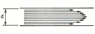
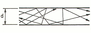
- the viscous or laminar regime: detectable with atmospheric pressure, the (many) molecules move in a near-compact manner thereby providing a flow and direction to the current. Thus, the physical effects deriving from the density of the gas, such as dynamic viscosity, prevail. The predominant direction of all the gas molecules is the same as the macroscopic direction of the gas current, as noted in the figure below. The flow is governed by the viscous forces and is constant over time;
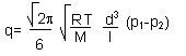
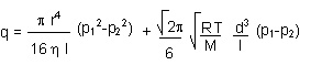
Poisseuille’s law provides an account of viscous flow through a tubular (circular) section:
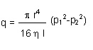
- Where r indicates the radius of the tube, l indicates length, ? indicates the dynamic viscosity of the gas, and p indicates the various pressures.
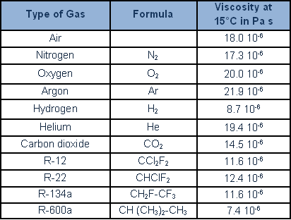
The following table provides the main dynamic viscosity of gases and refrigerants:
the molecular regime obtains where the density of the molecules is lower; that is, in the presence of high vacuum level conditions, and, in terms of mean free path, the probability of collision between molecules is lower than the probability of molecule-wall collision. In fact, particle-wall collision prevails. Due to elastic reflection phenomena and desorption, the direction of a particle of gas shall be random, and macroscopic slip therefore does not obtain. The motion of the fluid obtains chaotically; the trajectories are not orderly, as opposed to the laminar regime.
The formula governing the molecular regime is as follows:
Where R indicates the constant of ideal gases, T indicates the absolute temperature, M indicates relative mass, d indicates the diameter of the piping, l indicates length, and p indicates pressures.
- the Knudsen (transitional) regime is not readily definable, because it is hard to say to which laws the gases transiting from viscous to molecular flow (or vice versa) are subject.
![]()
A formula, as sum of the contributions of the other two regimes, may be arrived at.
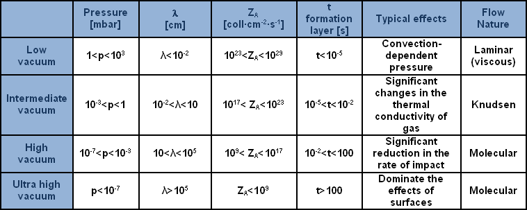
To better understand the typical regions of vacuum and of flow obtaining in a leak, which is helpful for selecting a process or for rapidly deciding on the most suitable component, a breakdown was effected of the entire field of lower pressures (or, according to preferences, of vacuums) into regions, on the basis of the various typical effects and the nature of the flow, as may be noted in the table provided.
The table provides a breakdown of the regions of the vacuum with reference to pressure, indicating characteristics and typical effects. The symbol, ? (lambda) signifies ‘mean free path’: the mean length of the path taken by a molecule between one collision and the next; ZA indicates the number of collisions of the molecule with a surface area in a unit of time; lastly, t stratum formation indicates the time required to cover a clean surface area in vacuum conditions with a stratum of gas of the thickness of one molecule.
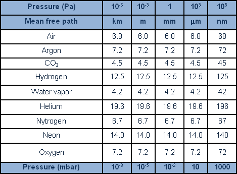
The following table linking the mean free path of different gases at different pressures.